Embassy
Prerequisites
The Rust toolchain
In order to install the tools needed to compile Rust code, follow the next steps, depending on your operating system.
Linux
Run the this command in terminal:
curl --proto '=https' --tlsv1.2 -sSf https://sh.rustup.rs | sh
This downloads and runs rustup-init.sh, which in turn downloads and runs the correct version of the rustup-init executable for your platform.
Windows
Download the respective executable:
You may be prompted to install Visual Studio C++ Build tools. If so, follow the instructions from the previous link.
Even if Visual Studio is already on your machine, rustup will not verify if the required components are present. If you experience issues with the rustup installation on Windows, please follow these instructions to manually add the missing components.
The last step is to run rustup --version in terminal. If everything went well, you should see an output similar to this:
rustup 1.28.1 (f9edccde0 2025-03-05)
info: This is the version for the rustup toolchain manager, not the rustc compiler.
info: The currently active `rustc` version is `rustc 1.85.0 (4d91de4e4 2025-02-17)`
probe-rs
probe-rs is an embedded debugging and target interaction toolkit. It enables its user to program and debug microcontrollers via a debug probe. To install it, please follow the official installation tutorial.
If you are on Linux you will also need to add this udev file in /etc/udev/rules.d. Then, run:
udevadm control --reload # to ensure the new rules are used.

udevadm trigger # to ensure the new rules are applied to already added devices.
Hardware support overview
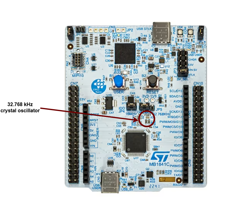
This is a top view of the board we will use for this workshop:

STM32 Nucleo-U545RE-Q
The "brains" of the board is represented by the STM32 Nucleo-U545RE-Q, a compact microcontroller with based on Arm Cortex-M33, running at up to 160 MHz. It features 272 KB SRAM, 512 KB flash storage. It includes 51 GPIO pins, 4 I²C buses, 3 SPI channels, 2 UARTs, USB 2.0 FS, and CAN (FDCAN), on the analog side, it integrates a 12‑bit ADC, a 14‑bit ADC, and dual 12‑bit DACs, complemented by advanced math and signal‑processing functions and security enhancements include Arm TrustZone and OTP memory. This makes it ideal for IoT and embedded applications.
Documentation
GPIO
What is GPIO?
General-Purpose Input/Output, or GPIO, is an essential part of embedded systems that serves as a vital conduit between microcontrollers and microprocessors and the outside world. A microcontroller or microprocessor's group of pins that can each be set to operate as an input or an output is referred to as GPIO. The purpose of these pins is to interface external components, including actuators, displays, sensors, and other devices, so that the embedded system may communicate with its surroundings. Standardized communication protocols like SPI, I2C, PCM, PWM, and serial communication may be directly supported by some GPIO pins. There are two varieties of GPIO pins: digital and analog.
Configuring GPIO Pins
GPIO pins can be used as outputs (LEDs, motors, buzzers) or as inputs (buttons, sensors).
The STM32U545 controls the GPIO pins through several GPIO Ports (PortA, PortB, PortC, PortD, PortE, etc.). Using GPIOs implies configuring the:
- MODER - connects the outer GPIO pin to one of the:
- internal
GPIOperipheral asinput - internal
GPIOperipheral asoutput - one of the alternate function peripheral (further selected by the Alternate Function Multiplexer)
- the
ADCperipheral
- internal
- Electrical Configuration - manages the physical pin on the outside of the chip. It decides the electrical behavior of the pad, such as whether it has a pull‑up or pull‑down resistor, whether it drives strongly or weakly, and whether it is push‑pull or open‑drain.
- Alternate Function Multiplexer - connects the internal peripherals to the outside pins. Each pin can be switched to different functions. For example, a single pin can be used as:
- a
UARTtransmit line - an
I2Cdata line - an
SPIclock or data line - a
TIMtimer channel - a
PWMtimer channel - ...
- a
- GPIO Input/Output - this is the simple digital interface that developers use when they want to read or write a pin directly in software. It’s what you use to toggle an LED or read a button.
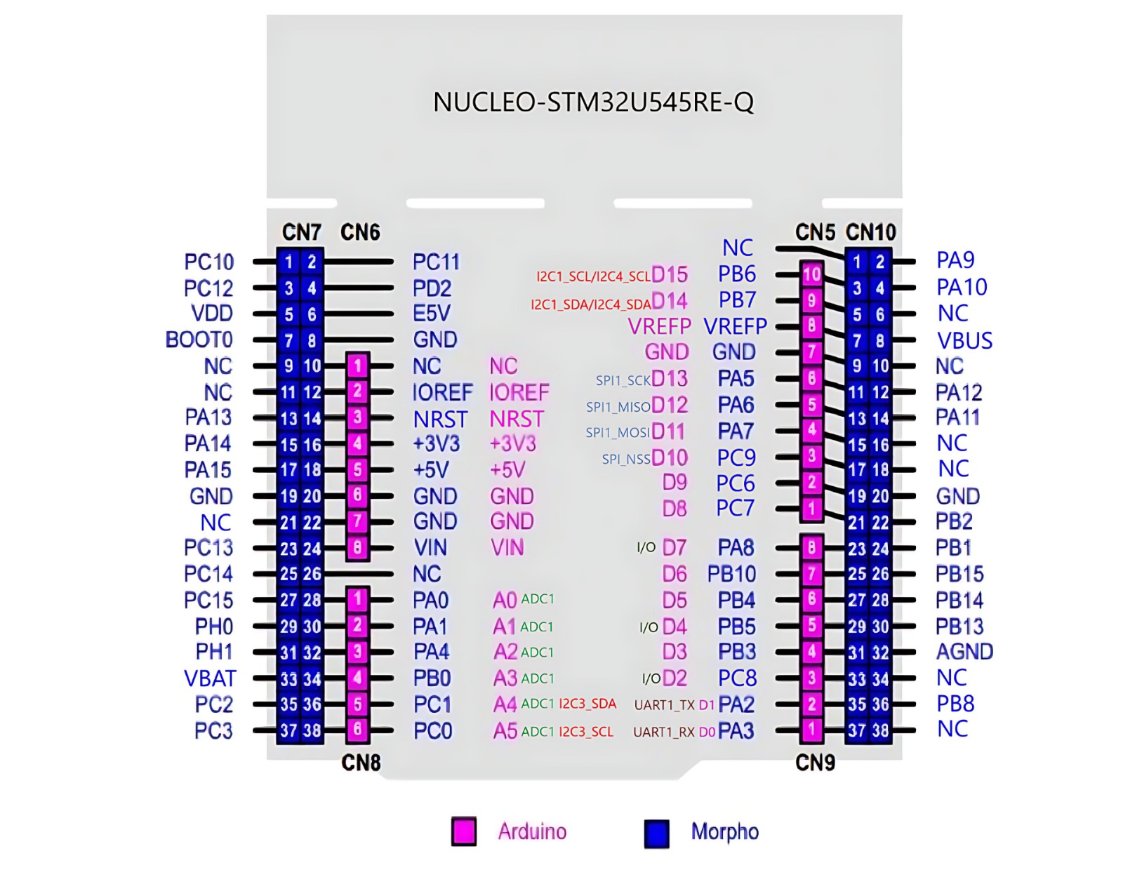
When you look at an STM32 Nucleo-U545RE-Q development board, you'll notice two sets of male pin headers. These are designed to give you two different ways to access the microcontroller's (MCU) pins.
-
ST Morpho Headers: These are the two long, outer rows of pins (e.g., CN7 and CN10). They are a superset designed to expose all the I/O pins of the STM32 microcontroller for complete access and flexibility.
-
Arduino Headers: These are the four inner headers (e.g., CN5, CN6, CN8, CN9). They are a subset of the ST morpho pins. Their layout is standardized to match the Arduino Uno R3, allowing you to easily connect and use existing Arduino shields.
In short, every Arduino pin is also available on the ST morpho headers, but the morpho headers provide access to many more pins that are not part of the Arduino layout.
Timing
In embedded applications, keeping track of time is crucial. Even for the simple task of blinking an LED at a certain time interval, we need a reference of time that is constant and precise.
Clocks
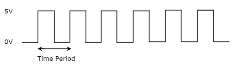
A clock is a piece of hardware that provides us with that reference. Its purpose is to oscillate at a fixed frequency and provide a signal that switches from high to low at a fixed interval.
The most precise type of clock on the STM32 Nucleo-U545RE-Q is the High-Speed External oscillator (HSE). The reason why it is so accurate is because it uses the crystal’s natural vibration frequency to generate the clock signal. This oscillator is usually external to the microcontroller itself, requiring a crystal or external clock source connected to the HSE pins.
The processor also provides several internal RC oscillators (HSI, MSI, LSI), which are less accurate because they rely on resistor-capacitor timing rather than quartz resonance. These internal clocks are useful when small variations in clock pulses are acceptable, or when minimizing external components is important.
The STM32 Nucleo-U545RE-Q does not have a built-in crystal frequency. Instead, the board designer selects an appropriate crystal (commonly 8 MHz, 16 MHz, or 24 MHz) to drive the HSE, depending on the application requirements.
Counters
A counter in electronics is a tool that tracks numbers, typically by adding or subtracting one each time the clock ticks. When it reaches its maximum (or minimum) value, it resets or wraps around. This reset is called an "overflow" (when counting up) or "underflow" (when counting down). Some counters can also switch between counting up and down based on control signals.
A regular counter on 8 bits would count up from 0 to 255, then loop back to 0 and continue counting.
In theory a counter is associated with 3 registers:
| Register | Description |
|---|---|
value | the current value of the counter |
direction | whether the counter is counting UP or DOWN |
reset | if the direction is UP, the value at which the counter resets to 0; if the direction is DOWN, the value at which the counter reset after reaching 0 |

The way the counter works here is that it increments/decrements every clock cycle and checks whether or not it has reached its reset value. If is has, then it resets to its initial value and starts all over again.
SysTick
The ARM Cortex-M33 used by STM32U545 both use the SysTick time counter to keep track of time. This counter is decremented every microsecond, and when it reaches 0, it triggers an exception and then resets.
SYST_CVRregister - the value of the timer itselfSYST_RVRregister - the reset valueSYST_CSR_SETregister:ENABLEfield - enable/disable the counterTICKINTfield - enable/disable exception on reaching 0
Timers
The simplest way to make a processor wait is to ask the processor to skip a clock cycle a number of times, or by calling the processor instruction nop (no operation) in a loop.
This method is not ideal, since the nop instruction stalls the processor and wastes valuable time that could otherwise be used to do other things in the meantime. To optimize this, we can use alarms.
An alarm is a counter that triggers an interrupt every time it reaches a certain value. This way, an alarm can be set to trigger after a specific interval of time, and while the alarm hardware is running in the background, the main program can continue executing instructions, and so it is not blocked. When the alarm reaches the chosen value, it goes off and triggers an interrupt that can then be handled in its specific Interrupt Service Routine (ISR).

The RP2350 timer and the RP2040's are fully monotonic, meaning they can never truly overflow. Their value is stored on 64 bits and incremented every 1 microsecond, ensuring precise and consistent timekeeping. This means the last value they can increment to before overflowing is 264‑1, which is equivalent to roughly 500,000 years. RP2040 and RP2350 support 4 different alarms (TIMERx_IRQ_0/1/2/3), which can be used independently, allowing for multiple timed events or tasks to be managed simultaneously.
The RP2350 provides two timer peripherals, while the RP2040 provides only one.
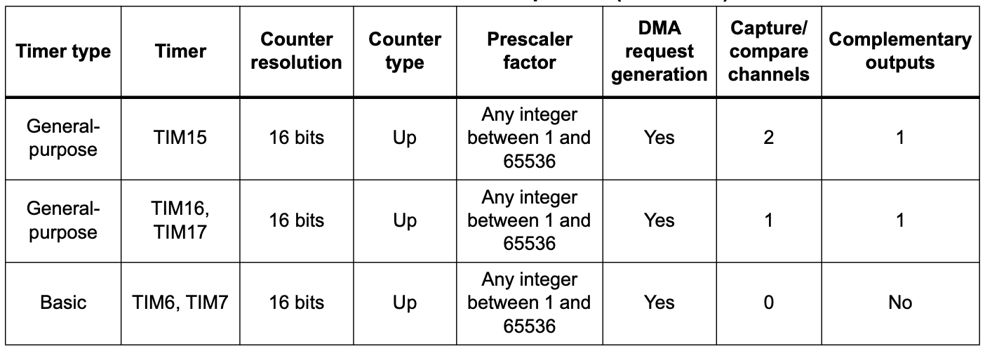
The STM32U5, by contrast, does not use a single 64‑bit monotonic timer. Instead, it provides a set of general‑purpose 16‑bit and 32‑bit timers (TIMx) as well as advanced timers for motor control and low‑power timers for energy‑sensitive applications. These timers can be configured with prescalers and auto‑reload registers to generate periodic interrupts, PWM signals, input capture, or output compare events. Unlike the RP2040 and RP2350’s unified 64‑bit microsecond counter, STM32 timers can overflow depending on their bit‑width (e.g., a 16‑bit timer rolls over after 65,535 counts). To achieve long‑duration or monotonic timekeeping, software typically chains timers or uses the SysTick timer in combination with interrupts.
Analog and Digital Signals
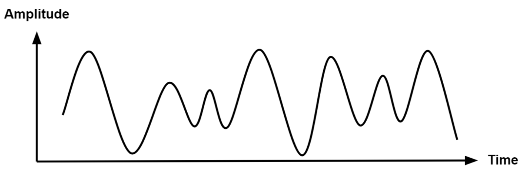
Analog signals are a representation of real-world data. They communicate information in a continuous function of time. They are smooth and time-varying waves, and contain an infinite number of values within the continuous range. An example of an analog signal would be sound, or the human voice.
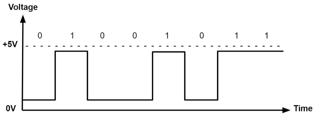
Digital signals are a discrete representation of data. They are represented by a sequence of binary values, taken from a finite set of possible numbers. They are square and discrete waves. In most cases, they are represented by two values: 0 and 1 (or 0V and 5V). Digital representation of signals is usually used in hardware.
Pulse-Width Modulation (PWM)
Up to now, we learned to turn an LED on and off, or in other words, set a LED's intensity to 100% or 0%. What if we wanted to turn on the LED only at 50% intensity? We only have a two-level digital value, 0 or 1, so technically a value of 0.5 is not possible. What we can do is simulate this analog signal, so that it looks like the LED is at half intensity.
Pulse-Width Modulation is a method of simulating an analog signal using a digital one, by varying the width of the generated square wave.
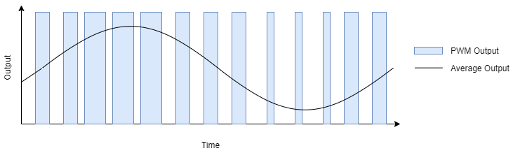
We can think of the simulated analog signal being directly proportional to the change in digital signal pulse size. The larger the square wave at a given period T, the higher the average analog amplitude output for that period.
The duty cycle of the signal is the percentage of time per period that the signal is high.
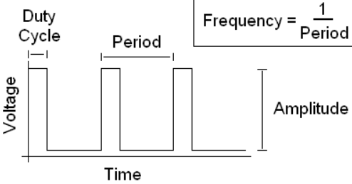
So if we wanted our led to be at 50% intensity, we would choose a duty cycle of 50%. By quickly switching between high and low, the led appears to the human eye as being at only 50% intensity, when in reality, it's only on at max intensity 50% of the time, and off the rest of the time.
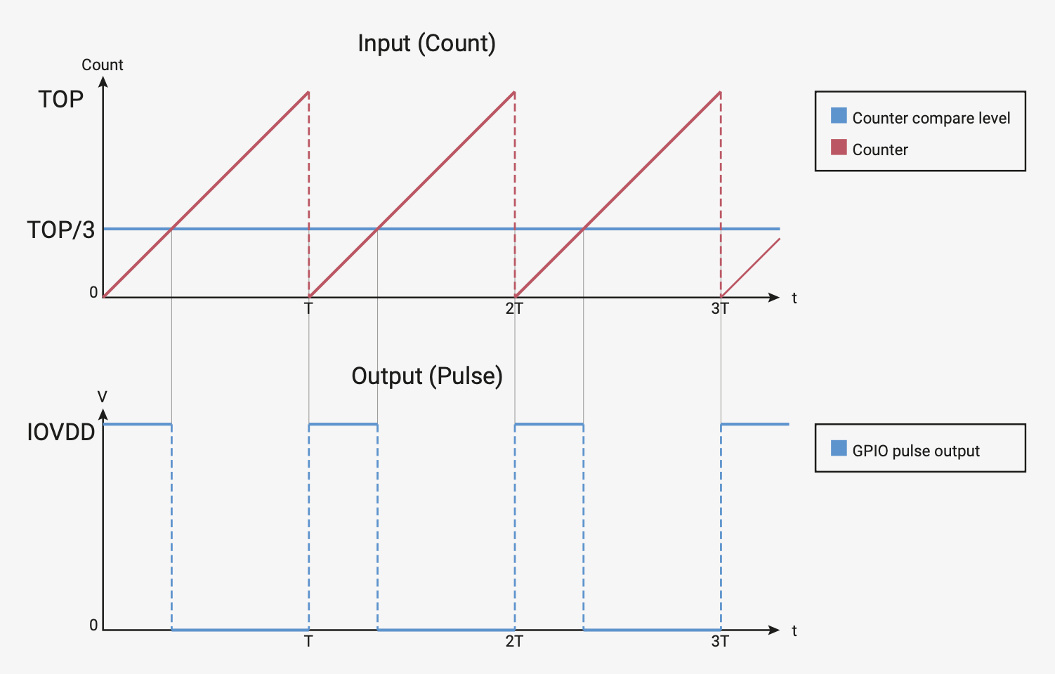
On the STM32U545, PWM generation is handled by the timer peripherals (TIMx), where each channel uses a counter (TIMx_CNT), a compare register (TIMx_CCRy), and an auto‑reload register (TIMx_ARR) to define the duty cycle and period.
TIMx_CNT- the actual value of the counterTIMx_CCRy- the compare value for channel y (this sets the duty cycle)TIMx_ARR- the auto‑reload value, the maximum count before the counter resets (this sets the period)
When TIMx_CNT is reset (0), the output signal is set to 1 (active). The counter counts up until it reaches TIMx_CCRy, after which the output signal becomes 0 (inactive). The counter continues to count until it reaches TIMx_ARR, then it resets to 0 and the signal becomes 1 again.
On STM32U545, PWM signals are generated by the timer peripherals (TIMx). Each timer provides multiple channels, and each channel can be mapped to specific GPIO pins through the alternate function system.
| Arduino connector | STM32 pin | PWMs |
|---|---|---|
D3 | PB3 | TIM2_CH2 (Timer 2 PWM Channel 2) |
D5 | PB4 | TIM3_CH1 (Timer 3 PWM Channel 1) |
D6 | PB10 | TIM2_CH3 (Timer 2 PWM Channel 3) |
D9 | PC6 | TIM3_CH1 (Timer 3 PWM Channel 1) |
D10 | PC9 | TIM3_CH4 (Timer 3 PWM Channel 4) |
D11 | PA7 | TIM3_CH2(Timer 3 PWM Channel 2) |
You can find more details about the pins in the user manual of the board(page 33)
Examples of hardware controlled through PWM
- leds
- motors
- buzzers
- RGB leds (what we will be using for this lab)
An RGB LED is a led that can emit any color, using a combination of red, green and blue light. On the inside, it's actually made up of 3 separate leds:
- R led - to control the intensity of the red light
- G led - to control the intensity of the green light
- B led - to control the intensity of the blue light
By using PWM on the R, G and B leds, we can control each of their intensity to represent any color.
For example, if we wanted to create the color purple, we would set the intensity of red and blue to 100%, and the intensity of green to 0%.
There are two different types of RGB LEDs:
- common cathode: all LED cathodes are connected together. A LOW signal means off, and a HIGH signal means on at max intensity.
- common anode: all LED anodes are connected together. A LOW signal means on at max intensity, and a HIGH signal means off.
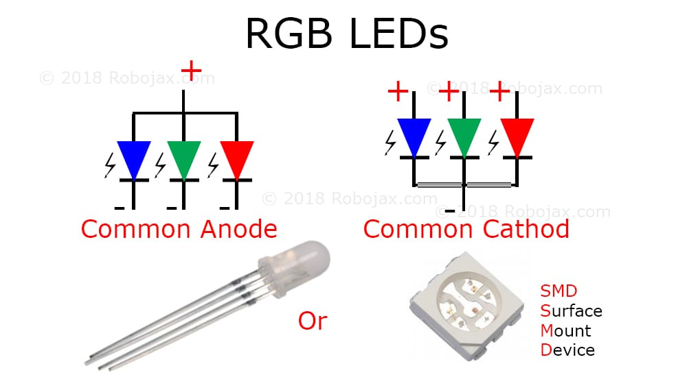
For this lab, we will be using common anode RGB LEDs, which means that the PWM signal should be opposite. 0 will be 100% intensity, and 1 will be 0% intensity.
How to wire an RGB LED
The RGB LED that the board provides is signaled with labels RGB_BLUE (blue), RGB_GREEN (green) and RGB_RED (red) in the connectors section.

How to wire a servo motor
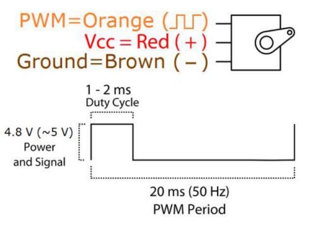
A servo motor is a motor that can be controlled with PWM. It has an arm that can be rotated to a specific angle, depending on the PWM signal it receives.
A servo motor has three wires:
- Power - usually red, connected to a voltage source (5V)
- Ground - usually black, connected to the ground
- Signal - usually orange, connected to a PWM pin
The board provides the connectors for the servo motor. These connectors are labeled GND, PWR, and SIG in the connectors section.
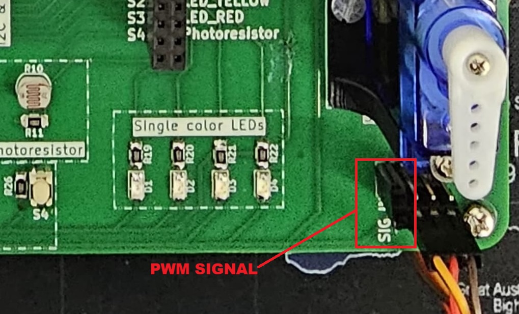
To wire the servo motor to the STM32 Nucleo-U545RE-Q, note that the servo’s PWR, GND, and SIG lines are already connected to the lab board. The only additional step is to place a jumper wire from the SIG connector of the the lab board to a suitable PWM-capable pin on the STM32 Nucleo-U545RE-Q.
PWM in Embassy-rs
First, we need a reference to all peripherals, as usual.
// Initialize peripherals
let peripherals = embassy_stm32::init(Default::default());
use embassy_stm32::timer::simple_pwm::{PwmPin, SimplePwm};
use embassy_stm32::peripherals::TIM2;
use embassy_stm32::timer::Ch1;

    // Configure PA0 as TIM2_CH1 PWM output
    let led_pwm_pin: PwmPin<'_, TIM2, Ch1> = PwmPin::new(p.PA0, OutputType::PushPull);
PA0→ the physical GPIO pin you want to use.TIM2→ the timer peripheral that will generate the PWM signal.Ch1→ the channel of that timer (channel 1).PwmPin::new_ch1→ ties PA0 to TIM2 channel 1’s output.OutputType::PushPull→ configures the electrical drive mode of the pin.
let mut pwm = SimplePwm::new(
    p.TIM2,              // Timer 2 peripheral
    Some(led_pwm_pin),   // Channel 1 output (PA0)
    None,                // Channel 2 not used
    None,                // Channel 3 not used
    None,                // Channel 4 not used
    khz(1),              // PWM frequency = 1 kHz
    Default::default(),  // Default configuration
);
The code above is an example for PA0 with TIM2_CH1. You need to modify the timer, channel, and pin depending on which PWM‑capable pin you want to use!
If we decide to modify the duty cycle of the PWM, we can update it directly on the channel:
let mut ch1 = pwm.ch1(); // Get handle for channel 1
ch1.enable();

// Set duty cycle to 50%
ch1.set_duty_cycle_percent(50);

// Later, change duty cycle to 10%
ch1.set_duty_cycle_percent(10);
Controlling a Servo Motor Using PWM
Just like controlling other hardware through PWM, we start by initializing the peripherals.
Servos typically expect a 50 Hz PWM signal, which corresponds to a 20 ms period.
Servos interpret PWM signals based on the pulse width rather than just frequency:
Period: The total time for one PWM cycle, which is 20 ms (50 Hz).Minimum Pulse Width: Typically 0.5 ms, which corresponds to a servo position of 0 degrees.Maximum Pulse Width: Typically 2.5 ms, which corresponds to a servo position of 180 degrees.
// Initialize peripherals
let peripherals = embassy_stm32::init(Default::default());
At 50 Hz, the PWM period is:
For a given pulse width the duty cycle percentage is:
The function set_duty_cycle_fraction(num, den) expects a fraction representing the duty cycle.
For example, to generate a of 2.5ms,
That means set_duty_cycle_fraction(125, 1000)
- For = 0.5ms:
That means set_duty_cycle_fraction(25, 1000)
We use ‰ for accuracy, as the PWM works with integer numbers and % is not accurate enough.
Now, let's implement it in Rust:
// Set the PWM pin
let servo_pin = PwmPin::new_ch1(p.PA0, OutputType::PushPull);

// 50 Hz PWM (20 ms period)
let mut pwm = SimplePwm::new(
    p.TIM2,
    Some(servo_pin),
    None,
    None,
    None,
    hz(50),
    Default::default(),
);

// Enable the PWM channel
    let mut ch1 = pwm.ch1();
    ch1.enable();

const MIN_PERIOD_US: u32 = 500;
const MAX_PERIOD_US: u32 = 2500;
const PERIOD_US: u32 = 20000;

let min_value = (MIN_PERIOD_US * 1000) / PERIOD_US;
let max_value = (MAX_PERIOD_US * 1000) / PERIOD_US;

    // Main loop to move the servo back and forth
    loop {
        // At 50 Hz, T = 20 ms. A 2.5 ms pulse means 2.5/20 = 12.5% duty cycle.
        set_duty_cycle_fraction(max_value as u16, 1000); // sets the servo to set servo to ~180°.
        // Wait 1 second before moving back
        // A 0.5 ms pulse means 0.5/20 = 2.5% duty cycle.
        set_duty_cycle_fraction(min_value as u16, 1000); // sets the servo to set servo to ~0°.
        // Wait 1 second before repeating
    }
Analog-to-Digital Converter (ADC)
Now we know how to represent an analog signal using digital signals. There are plenty of cases in which we need to know how to transform an analog signal into a digital one, for example a temperature reading, or the voice of a person. This means that we need to correctly represent a continuous wave of infinite values to a discrete wave of a finite set of values. For this, we need to sample the analog signal periodically, in other words to measure the analog signal at a fixed interval of time. This is done by using an Analog-to-Digital converter.
The ADC has two important parameters that define the quality of the signal representation:
| Parameter | Description | Impact on quality |
|---|---|---|
| Sampling Rate | Frequency at which a new sample is read | The higher the sampling rate, the more samples we get, so the more accurate the representation of the signal |
| Resolution | Number of bits which we can use in order to store the value of the sample | The higher the resolution, the more values we can store, so the more accurate the representation |
For example, a resolution of 8 bits means that we can approximate the analog signal to a value from 0 to 255, where 0 means 0 volts and 255 represents the ADC reference voltage (maximum voltage the ADC can measure).

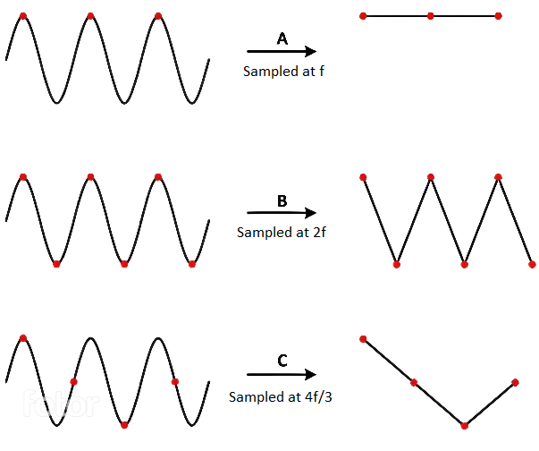
Nyquist-Shannon Sampling Theorem
The Nyquist-Shannon sampling theorem serves as a bridge between continuous-time signals and discrete-time signals. It establishes a link between the frequency range of a signal and the sample rate required to avoid a type of distortion called aliasing. Aliasing occurs when a signal is not sampled fast enough to construct an accurate waveform representation.
For an analog signal to be represented without loss of information, the conversion needs to satisfy the following formula:
The analog signal needs to be sampled at a frequency greater than twice the maximum frequency of the signal. In other words, we must sample at least twice per cycle.
Examples of analog sensors
- temperature sensor
- potentiometer
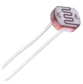
- photoresistor
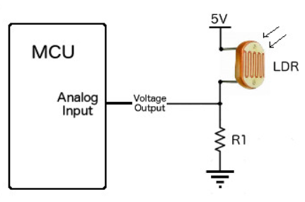
A photoresistor (or photocell) is a sensor that measures the intensity of light around it. Its internal resistance varies depending on the light hitting its surface; therefore, the more light there is, the lower the resistance will be.
How to wire a photoresistor
The photoresistor that the board provides is signaled with the label PHOTORESISTOR in the connectors section.
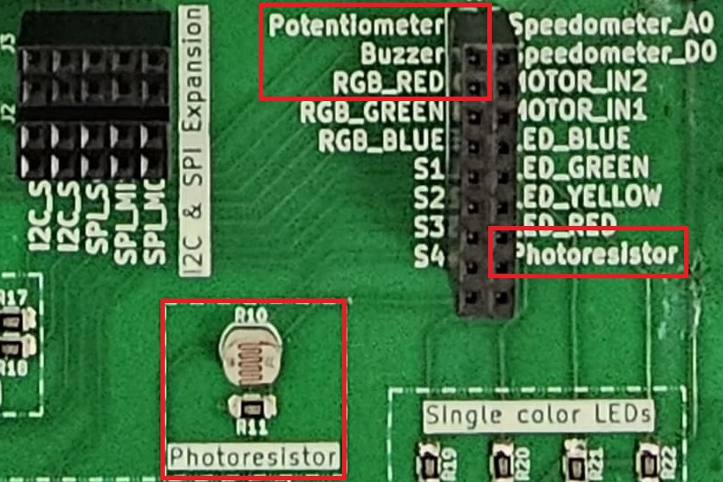
To wire a photoresistor on your board at home, you need to connect one leg to GND and the other leg to a voltage divider.
In our case:
- will be the voltage at the ADC pin on the MCU
- will be the voltage at the GPIO pin the photoresistor is tied to
- is the variable resistance of the photoresistor
- is a resistance compatible with our photoresistor (in our case, 10k )
This way, the ADC pin measures the photoresistor's resistance, without the risk of a short-circuit.
ADC in Embassy-rs
On the STM32, the ADC peripheral does not use a FIFO interrupt like the RP2. Instead, each ADC (ADC1, ADC2, etc.) can be configured directly, and Embassy provides a driver that handles resolution, averaging, and sample time for you. All we need to do is create the ADC driver, configure it, and then bind it to the pin we want to read from.
| Arduino connector | STM32 pin | ADC |
|---|---|---|
A0 | PA0 | ADC1_IN5(ADC1 Channel 5) |
A1 | PA1 | ADC1_IN6 (ADC1 Channel 6) |
A2 | PA4 | ADC1_IN9 (ADC1 Channel 9) |
A3 | PB0 | ADC1_IN15 (ADC1 Channel 15) |
A4 | PC1 | ADC1_IN2 (ADC1 Channel 2) |
A5 | PC0 | ADC1_IN1 (ADC1 Channel 1) |
// ---- fn main() ----

let p = embassy_stm32::init(Default::default());

// Create ADC driver on ADCx
let mut adc = adc::Adc::new(p.ADCx);

// Configure resolution, averaging, and sample time
adc.set_resolution(adc::Resolution::BITS14);
adc.set_averaging(adc::Averaging::Samples1024);
adc.set_sample_time(adc::SampleTime::CYCLES160_5);

const MAX_VALUE: u32 = adc::resolution_to_max_count(adc::Resolution::BITS14);
When reading the ADC, it is important to distinguish between the maximum digital count and the maximum input voltage. The function
const MAX_VALUE: u32 = adc::resolution_to_max_count(adc::Resolution::BITS14);
returns the largest integer code that the ADC can produce for a 14‑bit conversion.
- For a 14‑bit ADC, the digital output spans from 0 to
2^14 - 1 = 16383. MAX_VALUEwill therefore hold the value16383.- This is not the maximum voltage that the ADC can measure. The maximum voltage is determined by the reference voltage (e.g., 3.3 V), while
MAX_VALUEsimply represents the highest possible digital code.
Once we have the ADC and pin set up, we can start reading values from the pin. Here’s a simple loop that reads the raw ADC value, converts it to a voltage, and prints it:
loop {
    // Read a raw ADC value (blocking read)
    let level: u16 = adc.blocking_read(&mut adc_pin);
    let voltage = 3.3f32 * level as f32 / MAX_VALUE as f32;

    info!("Light sensor reading: {}, voltage: {}", level, voltage);

    // Wait a bit before reading again
    embassy_time::Timer::after_secs(1).await;
}
Inter-Integrated Circuit (I2C)
The Inter-Integrated Circuit (I2C) is a synchronous, multi-controller/multi-target communication protocol. Similarly to the SPI, it allows data transfer between a controller and one or more peripheral ICs, but it uses only 2 wires (1 data line and 1 clock line, making it half-duplex) and has a different way of addressing the peripherals: using the their unique addresses.
Configuration

I2C transmission uses 2 lines:
- SCL - Serial CLock line - clock is generated by the controller - used to synchronize communication between the controller and the targets
- SDA - Serial DAta line - carries data between the controller and the addressed target
- targets read data from SDA only when the clock is low
- targets write data to SDA only when the clock is high
The communication is half-duplex. This means that data is transmitted only in one direction at a time, since there is only one data line that can be used both for sending data to the target and receiving data from the target.
The SDA and SCL wires are never actually driven (set to LOW/HIGH) by the controller/peripherals. The line is controlled by either pulling the line low or releasing the line high.
When the line is pulled down, this means that it is tied directly to GND. This electronically translates to LOW.
When the line is released, or pulled up, this means that it ties back to 3V3 (which we can consider as being the "default" state of the wire) through a pull-up resistor. This electronically translates to HIGH.
This is called open-drain connection. You can read more about how it works here, at section 2.2.
Data transmission
Each target is associated with a unique address. The controller uses this address to initiate communication with that target. This address can either be 7 or 10 bits.
Initiation
Before the transmission, both the SCL and SDA lines are set to HIGH. First thing the controller does is to signal a start condition by pulling the SDA line to LOW. All targets understand that the communication is about to commence and listen on the SDA line. Next, the controller starts the clock and begins to write the address of the target it wants to talk to, followed by a command bit that signifies whether the controller wants to read from the target or write to it. Whichever target recognizes its address, responds with an ACK (acknowledged), by pulling the SDA to LOW. If no target responds and the SDA stays HIGH, then it is considered a NACK (not acknowledged). Afterwards, the data transmission can begin.
Transmission
Depending on the command bit (R/W), either the controller or the target begins to send data over the SDA line. Data is sent one byte at a time, and then acknowledged by the receiver. One sequence of a data byte and ack is called a frame.
During the communication, data can be:
- written to the
SDAline only whenSCLisLOWor - read from the
SDAline only whenSCLisHIGH.
End
To end the transmission, the controller signals a stop condition. This is done by releasing the SCL line to HIGH, and then also releasing the SDA line. Since data can be written only when SCL is LOW, the target understands that this is a special event, that means that the communication has ended.

For 10-bit addresses, the controller first issues a specific sequence of bits. This sequence is reserved, therefore targets with 7-bit addresses are prohibited from having addresses that start with this sequence. These bits mark the fact that the controller is attempting to initiate communication with a target with a 10-bit address, so all 7-bit targets ignore the SDA line once they recognize this sequence. After the special sequence, the controller sends the upper 2 bits of the address, then waits for an ack from the target(s) that have an address that begins with these 2 bits. Afterwards, it sends the rest of the address, and waits for an acknowledgement from the target.

I2C in Embassy
These are the I2C imports we will be using. We will use the functions provided by the embedded_hal crate, since these are standard and used by most frameworks.
use embassy_stm32::i2c::I2c;
use embassy_stm32::{bind_interrupts, i2c, peripherals};
We start by initializing the peripherals.
let peripherals = embassy_stm32::init(Default::default());
Next, we declare the pins we will be using for the SDA and SCL lines. We can find which pins of the STM32 Nucleo-U545RE-Q have these functions by looking at the pinout.
let sda = peripherals.PXn;
let scl = peripherals.PYm;
We then initialize our I2C instance, using the pins we defined earlier and a default configuration. It's recommended to use the asynchronous version, since it won't block the executor.
let mut i2c = I2c::new(peripherals.I2C1, sda, scl, Irqs, p.GPDMA1_CH0, p.GPDMA1_CH1, Default::default());
The first argument of the new function is the I2C channel that will be used. There are multiple I2C channels on the STM32 Nucleo-U545RE-Q, and depending on which pins we decided to use, we can see which channel they are on by looking at the pinout.
The Irqs variable refers to the interrupt that the I2C driver will use when handling transfers. We also need to bind this interrupt, which depends on the I2C channel we are working with.
bind_interrupts!(struct Irqs {
    I2C1_EV => i2c::EventInterruptHandler<peripherals::I2C1>;
    I2C1_ER => i2c::ErrorInterruptHandler<peripherals::I2C1>;
});
Reading from a target
To read from a target, we will be using the read_async function of the I2C driver.
The function takes 2 parameters:
- the address of the target we are attempting to receive the data from
- the receiving buffer in which we will store the data received from the target
The following example reads two bytes from the target of address 0x44.
const TARGET_ADDRESS: u16 = 0x44;
let mut rx_buf = [0x00u8; 2];
i2c.read(TARGET_ADDR, &mut rx_buf).await.unwrap();
Writing to a target
To write data to a target, we will be using the write_async function of the I2C driver.
This function also takes 2 parameters:
- the address of the target we are attempting to transmit the data to
- the transmitting buffer that contains the data we want to send to the target
The following example writes two bytes to the target of address 0x44.
const TARGET_ADDR: u16 = 0x44;
let tx_buf = [0x01, 0x05];
i2c.write(TARGET_ADDR, &tx_buf).await.unwrap();
We can also use write_read if we want to perform both a write and a read one after the other.
i2c.write_read(TARGET_ADDR, &tx_buf, &mut rx_buf).await.unwrap();
Tasks
As this is an embedded workshop, you will need to make several connections using the provided male-to-male wires. Do not power the board without asking an assistant if it is ok to do so.
Before you start with writing code, make sure you register your team in this spreadsheet.
A skeleton application, which prints "Hello" can be found in this repository. It should already include everything you will need for today's workshop, in regards of external dependencies. Go ahead and clone it locally. In order to run it, you will need to actually connect the LED to the specified pin, using one of the provided male-to-male cables. For the LED, you can use any of the exposed LED's labeled RED, GREEN, BLUE and YELLOW. Then you can run the following command:
cargo run --bin demo
Throughout this section, you will find multiple HINTs, please try to solve the tasks yourself. The hints should be there as a last resort, after you have spent a few minutes being stuck, and are not supposed to be a shortcut in order to speedrun the workshop. Keep in mind that you can only solve a task once, and once read, a hint cannot be unread.
Hi, I am new here!
For your first task, you will need to print your team's name in terminal using the defmt whenever you press any of the four buttons labeled S1, S2, S3 and S4.
Baby steps
You should begin by printing something in terminal. Take a look at the defmt book.
Use the button
Try to incorporate one button into your application. You will need to await a button press, and then print the message in a continuous loop. Check the Embassy's ExtiInput documentation. Try to use one of the asynchronous functions, as it will be easier to extend it. Make sure you don't forget to wire the button.
Now let's use 'em all
You can combine multiple futures using the select and join functions exposed by the embassy-futures crate.
Sing your own tune!
This task requires singing one song of your desire, using the active buzzer located on the board.
Configure the PWM
You will need to a PWM output pin. In order to do that, you will need to decide what pin to use, and figure out what PWM Channel it is using. In order to do that, you will need to consult the datasheet. The Embassy's PWM api can be consulted here.
A crumb of music theory?
In music, note duration can be
- whole note - lasts 4 beats
- half note - lasts 2 beats
- quarte note - lasts one beat
- eight note - lasts half a beat
- sixteenth note - last a quarter of a beat
Notes can also be dotted, which means that its duration is increased by half of its initial "play time". (e.g a dotted half note, which would usually last 2 beats will last 3 beats).
We already have implemented the Note enum for you, which you can find in the src/music.rs module. It has variants for every standard piano note, and the value of each variant is the frequency of the respective note.
A bunch of constants
Next, we will need to define the duration of a whole note. To do that, we will need to determine the tempo. The tempo differs from song to song, and it is measured in beats per minute. For now, we will use a 100 BPM tempo. Based on this, a whole note duration should be 4 x beat_duration_ms = 4 * (60_000 ms / TEMPO).
The microcontroller runs at 150 MHz. This frequency is quite high, and that will be a problem when trying to match a note frequency using a 64 divider to slow it down. You will need to do so using the PWM Config.
Playing one octave
Our representation of one song will be an array of tuples:
const SONG: [(Option<Note>, i8); LEN] = {
    (Some(Note::A0), 8),
    (Some(Note::B2), 4),
    (None, 1),
    ...
}
A song is composed of either notes or pauses, which is why we chose to use the Option enum, and we chose to represent its length as fractions of the whole note (meaning that a (None, 4) represents a pause of a quarter of a note and a (Some(Note::A2), 2) is a half note A2). We omitted the dotted notes, and to represent them, we will use the negative counterparts of the notes. Therefore, (Some(Note::C2), -2) will be treated as a dotted C2 half note.
In the music.rs module, you will find already defined an 8 note array that represents an octave. You will need to connect the buzzer to a pin, that you will configure as PWM output. Then, you need to iterate over the array and figure out the duration of the note based on the above mentioned convention and "play" it, by configuring the timer's frequency in order to get a signal of matching the note's frequency, and a duty cycle of 50%. In order to mimic a real instrument, for the last 10% of the note duration we will turn off the buzzer.
Even though there are no pause notes, handling them now will help you later.
Finally, some good music
Pick a song and try to play it. You can find some examples already implemented in C, using the same conventions here.
My own thermometer!
For this task, you need to implement a basic thermometer, that will read the ambient pressure and communicate it using the RGB LED. It will display a color ranging from blue to red, depending how close the temperature's value is to the minimum threshold (20°C) and the maximum threshold (35°C).
RGB LEDs are made of 3 separate LEDs (one for each color channel) that are controlled individually. They come in two different configurations:
The one on the board is a common anode, and because of that the LEDs are off when the signal is high, and are at maximum intensity when the signal is low.
Disco party
Start by making the LED fade from blue to red. Remember what you learned at the previous exercise about configuring a PWM channel and do not forget to wire the LED using the sockets labeled RGB_RED, RGB_GREEN and RGB_BLUE.
The temperature is rising
To read the temperature, we wil use the BMP280 temperature and pressure sensor. You can find its datasheet here, and we highly encourage you to open it. The interaction with the sensor will be handled by the bmp280 module. You will need to explore it a bit, in order to figure out what is it's api. The module exposes two submodules, i2c and spi, depending on the underlying communication protocol you want to use. For this workshop, we will use I2C, because it only requires you to connect the BMP_SCL and BMP_SDA to two I2C capable pins.
Instantiate the I2C bus providing the two pins SCA and SDL and the respective peripheral (I2C0 or I2C1) and a default config. Then instantiate the BMP280 and set the control options, (power mode and pressure and temperature oversampling rate). You will also need to bind the interrupt for the I2C peripheral (I2CX_EV and I2CX_ER, where X is the peripheral number), using the bind_interrupt! macro. You can find an example in its documentation.
The last step
Now, combine the two into a solution.
Smile and Wave!
For your last challenge, you will need to use the joystick, to wave the servo motor's arm. What you need to know, is that the joystick has 2 potentiometers "under the hood", one for each axis. You will need to configure the two ADC channels to read the joystick position, and use PWM to control the servomotor.
Ignore the fact that label shows an input voltage of 5V, and use the 3V3 to power it. Otherwise, you risk damaging the board.
For this task, you are on your own... Feel free to use the Documentation provided by us, the materials on Embassy available on the internet, including their official Github, or other repos. The only thing you get is this last HINT.